Welcome to visit Hoyogo website, let's connect the world together!
Customer service hotline:+86 13723413985 or 400 058 2288
As AI large language models (LLMs), high-performance computing (HPC), cloud computing, and data center networks continue to evolve, 400G, 800G, and even 1.6T optical modules are becoming increasingly widespread. Higher data rates require higher-frequency signal transmission, placing greater demands on PCB signal integrity, impedance control, and signal loss performance.
As the primary carrier for high-speed electrical signal transmission inside optical modules, PCBs must not only achieve precise impedance control but also use low-loss materials to reduce transmission loss and maintain signal integrity. As a result, low-loss materials have become an essential part of high-speed optical module PCB manufacturing.
As a professional optical module PCB manufacturer, HoYoGo specializes in the manufacture of high-reliability, high-speed PCBs. We provide customized multilayer optical module PCB manufacturing services to meet diverse customer requirements, delivering stable and reliable PCB manufacturing support for high-speed optical communication equipment.
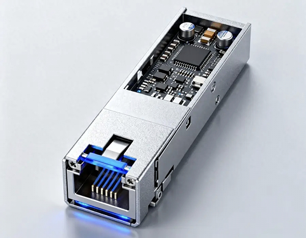
Common Types of Low-Loss Materials for Optical Module PCBs
Currently, high-speed optical module PCBs typically use low-loss copper-clad laminates specifically developed for high-speed digital circuits. These materials maintain stable dielectric properties and low transmission loss at high frequencies.
Common materials include the Panasonic MEGTRON series, the Isola I-Speed and Tachyon series, selected Rogers high-speed and high-frequency laminates, and high-performance materials from Chinese manufacturers. These materials are widely used in high-speed communication equipment and optical module applications.
Low-loss PCB materials typically offer the following characteristics:
1) Low and stable dielectric constant (Dk): Supports consistent impedance control and reliable high-speed signal transmission;
2) Low dissipation factor (Df): Helps reduce dielectric loss and signal attenuation during high-frequency transmission;
3) Consistent dielectric properties: Improve the transmission stability of high-speed differential signals;
4) Excellent thermal resistance and dimensional stability: Support multiple lamination cycles and lead-free soldering processes.
Selecting PCB Materials for Different Application Scenarios
Different transmission rates and applications place different performance requirements on PCB materials. Therefore, selecting the appropriate material requires balancing electrical performance, manufacturability, reliability, and cost.
For 100G and 200G optical modules, optimized high-speed FR-4 materials may still be suitable for certain applications when signal integrity requirements can be satisfied. This approach provides a balance between electrical performance and cost efficiency. For 400G and 800G optical modules, however, the increasing number of high-speed differential channels and higher signal frequencies generally require low-loss high-speed laminate materials to reduce insertion loss and improve signal integrity.
For 1.6T and future higher-speed optical modules, PCB performance requirements extend beyond the selection of low-loss dielectric materials. Advanced technologies such as ultra-low-profile copper foil, optimized stack-up structures, precise impedance control, and high-speed routing technologies are also required to support higher data transmission rates. Therefore, material selection is not simply about pursuing the lowest possible loss, but about achieving the optimal balance among electrical performance, manufacturing reliability, and overall cost.
PCB Manufacturing Requirements for Low-Loss Materials
During high-speed PCB manufacturing, critical processes including lamination, impedance control, copper foil selection, and drilling directly affect high-speed signal transmission performance. Therefore, tighter process control and higher manufacturing precision are required
First, high-speed laminate materials generally have relatively narrow lamination process windows. Lamination temperature, pressure, and heating profiles must be precisely controlled to ensure reliable interlayer bonding and prevent abnormal resin flow.
Second, high-speed PCBs typically require tighter impedance control. Trace width and spacing, etching compensation, and dielectric thickness uniformity all directly affect impedance accuracy and high-speed signal integrity.
In addition, to reduce high-frequency transmission loss, some high-speed PCBs use low-profile copper foil or very-low-profile and hyper-very-low-profile copper foil, commonly referred to as VLP and HVLP copper foil. These copper foils help reduce conductor loss associated with copper surface roughness and improve high-frequency signal transmission performance.
High-speed optical module PCBs often feature higher layer counts and greater routing density, placing stricter requirements on drilling accuracy, layer-to-layer registration, microvia fabrication, and automated optical inspection (AOI). Therefore, consistent product quality depends on mature manufacturing processes and a comprehensive quality control system.
HoYoGo is an international, professional, and reliable optical module PCB manufacturer specializing in the manufacture of 400G, 800G, and higher-speed optical module PCBs. HoYoGo combines its expertise in low-loss material processing, precision impedance control, and IPC-compliant manufacturing processes to provide stable and reliable PCB manufacturing support for high-speed optical modules, meeting the evolving requirements of data centers, AI servers, and high-speed optical communication equipment.


 English
 Français
 Deutsch
 Português
 Pусский
 中文
中文